|
Basic Tools
- Soldering iron
- Long-nose pliers
- Diagonal wire cutters
- Wire strippers
- Nut driver set
- Screwdriver set
- Hemostats
- 1/2 inch paintbrush
- Compressed air
Basic Supplies
- Electrical solder
- TV tuner cleaner
- Electrical tape
- WD-40
- Garbage bag ties (wire markers etc...)
- Assorted high voltage capacitors
- Assorted resistors
Beginning Equipment
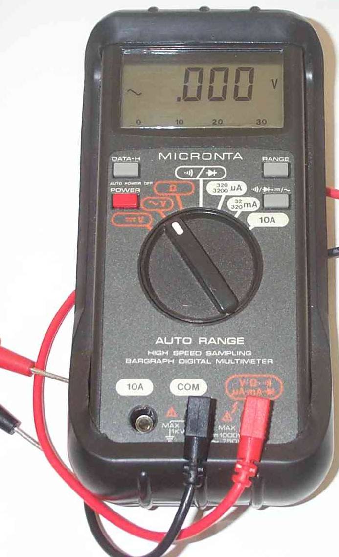
| Auto-Ranging Multimeter |
|
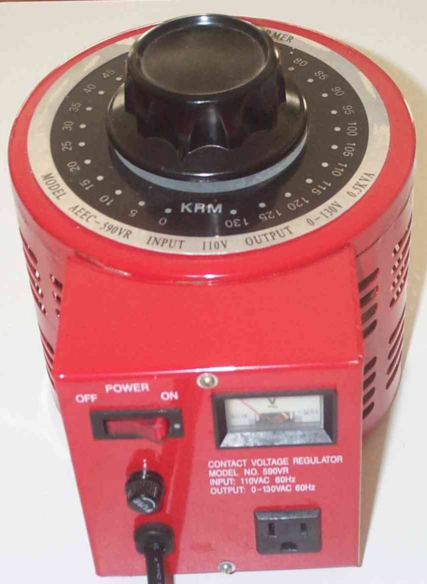
| Variable Voltage Regulator |
|
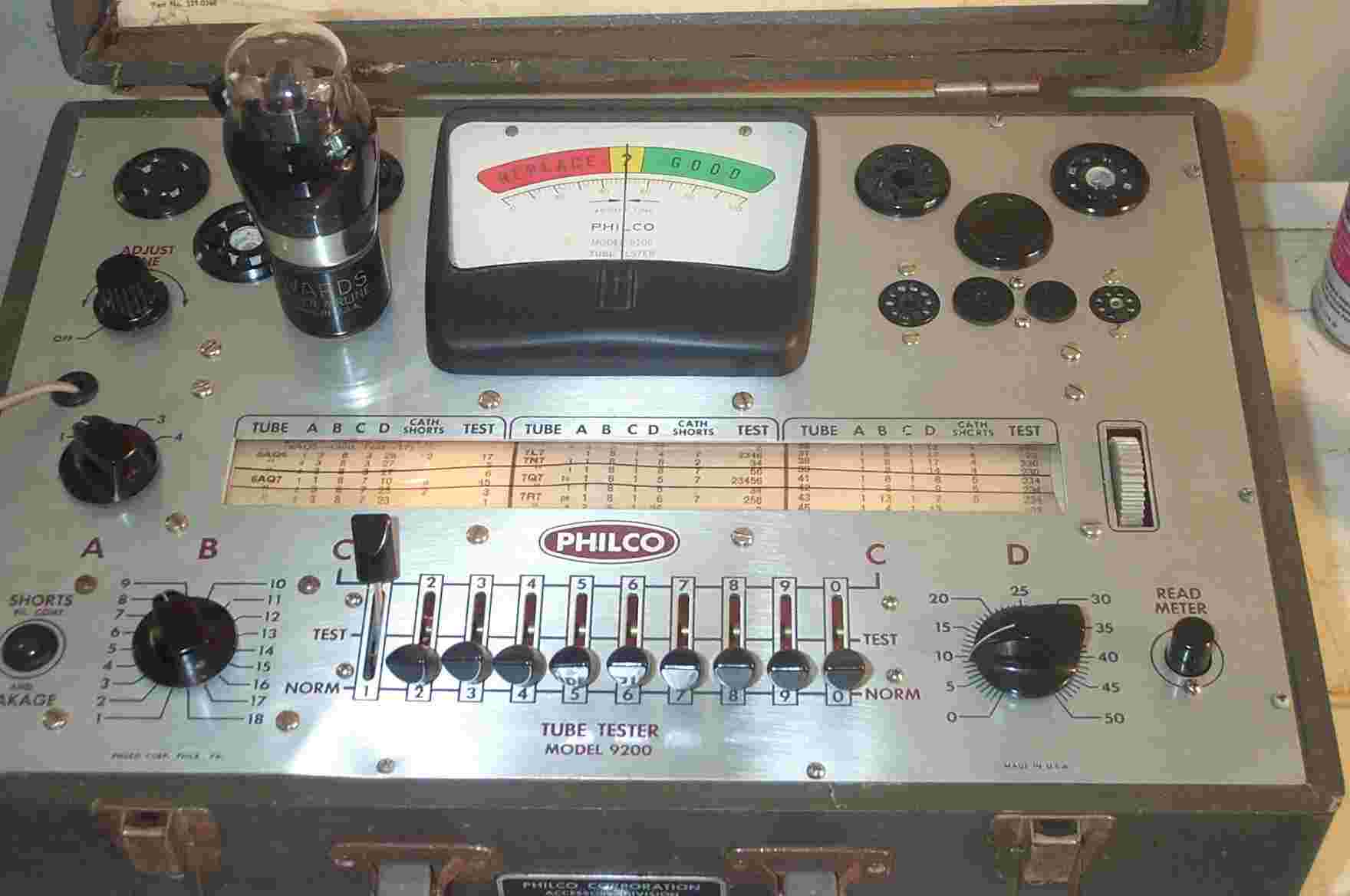
| Tube Tester |
|
|
 |
|
|
Tips!
(1.)
SAFETY FIRST. These old sets are high voltage appliances and the grounding should be considered
questionable. With voltage in excess of 300 volts in certain parts of the radio, SAFETY IS CRITICAL!
(2.)
If you are new to the hobby start with working radios! It is easier, at first,
and more satisfying to improve a working set than attempting to bring to life a set that will probably have multiple issues.
Mature into dealing with non-receiving sets.
(3.)
Ok, Great Aunt Russie's set does not work so you ignored tip #2. Fight the urge
to "fire-up" your new set. You may literally do just that! (Been there, got that t-shirt!)
(4.)
A good visual inspection is in order, which requires disassembly and some good
common sense. Clean the dust, look for disconnected wires, look for burned or charred components, and look for broken, blackened,
or loosely seated tubes.
(5.)
Clean the switches, contacts (especially tube pins), and moving components (tuning
capacitor) with a TV tuner cleaner (Radio Shack).
(6.)
Gradually bring the power up using a variable voltage regulator (pictured to
the right) or a homemade dim bulb series choke (see Phil's Antique Radios).
|
|
|
|
|
(7.)
Working or not, you will want to take some voltage reading on the tube pins.
Access Radio Forums, and we will guide you along. (Please be aware that some readings are in DC and some are in AC.)
(8.)
OK! It works pretty well but needs improving or it makes some noise but no reception.
You will now probably need an electrical schematic. The links on this site are excellent sources. If you cannot find your
radio please e-mail me. I have a complete set of Rider's Perpetual Trouble Shooter's Manuals.
(9.)
The percentages say your old set hums; perhaps loudly. TURN THAT
BABY OFF. My very good guess is deteriorated electrolytic capacitors. You now need a schematic and a source for the caps (see
RELATED LINKS). Remember, electrolytic capacitors must be connected with the correct polarity (positive-to-positive and negative-to-negative).
If you get this wrong you will certainly see a drama and possibly ruin other components (ask me how I know).
(10.)
My stance: ALWAYS replace ALL capacitors and ALL resistors. That way you
start from a known! There are those, with a great deal more experience than me, who disagree. Their preference is to replace
only what tests bad leaving the set as original as possible. I can respect that preference though, unquestionably,
modern components are far superior to those of the 1930s.
(11.)
More to come.
|
|
|
|
|